


| Power Supply: | AC |
|---|---|
| Model Number: | 130ST-M10020 |
| Voltage: | 220V |
| Motor Type: | servo motor |
| The flange: | 130mm |
| power: | 2.0KW |
| Output torque: | 10Nm |
| speed: | 2000 rpm |
| Unit Type: | piece |
| Package Size: | 30cm x 25cm x 10cm (11.81in x 9.84in x 3.94in) |
| Package Weight: | 16.5kg (36.38lb.) |
Quick Details
Specifications
Affordable servo drive and servo motor 2.0 KW, 10 nm, 130 flange, send 3 rice noodle!


Servo drive main control mode:
1, position pulse control: there are three kinds of pulse plus direction (CP + DIR); positive and negative control (CW + CCW); 90 ° orthogonal pulse (A + B).
2, analog speed control, analog 0-10V voltage control motor speed, you can achieve positive and negative and return to zero (or quasi-stop) function.
3, the internal speed control, by setting the drive parameters to specify the motor speed. Up to 8 steps can be set in advance.
4, the location of fixed length control, by setting the parameters of the drive to specify the motor movement distance and speed, you can achieve positive and negative movement.
5, to achieve the spindle servo function, you can achieve speed control and position control switching, quasi-stop function. (Note: need this function, please contact customer service, universal type is not with this function.)
A customer asked:
Why are your prices doing so low? What about product quality?
1: In management, we use flat management, making the operating costs greatly reduced.
2: We use the network direct sales model, reduce the cost of intermediate links will leave the profits to customers.
3: Components We are using the world famous brands, to ensure stable and reliable drive performance.
4: PCB process we use the immersion process, SMT chip processing.
Servo drive main core components:
1: using TI's (DSP) digital signal processor and ALTERA complex programmable logic device (CPLD) as an arithmetic unit


2: the filter capacitor used in aluminum electrolytic capacitors imported from Japan.

3: corriente sensor usando Honeywell
4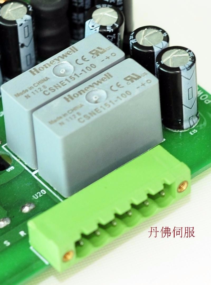

4: the Japanese MITSUBISHI intelligent power module (IPM)


5: PCB board using immersion gold process

6: all the aluminum alloy shell, the cooling effect is very good.
7: TAMAGAWA incremental encoder motor servo in Japan


Product List:
1, a servo motor
2, a servo drive
3, one encoder line (3 meters)
4, a motor power cord (3 meters)
5, 25 core parallel port one
6, a manual
Motor material
1 the use of the air outlet is a strong brand, (Du Jin)
2 enamel covered wire using 180T, high temperature 180 degrees
3. Rare earth permanent magnetic material is a listed company in Jiangxi, the model for the sh-t, every piece of magnetic flux difference of not more than 1% (stability), in 150 high temperature oven to bake for 2 hours, repeated three times then tested permanent magnetic materials, the demagnetization rate does not exceed 3%
Servo drive type:DA98
Power: the servo driver is suitable for 1.2KW~2.6KW motor.
Independent research and development of a new generation of full digital AC servo driver, the main use of the latest digital signal processor DSP technology and large-scale FPGA programming technology as the core arithmetic unit and smart intelligent power module (IPM), with fast response, perfect protection and high reliability a series of advantages.
Speed ratio of 1:5000, from low speed to high speed have a stable torque characteristics
Control positioning accuracy of + 0.01%, 300% overload capacity
Using space vector control algorithm, than the ordinary SPWM generated greater torque, less noise
Perfect protection function: over current, over voltage, over heat and encoder fault
A variety of display functions: including motor speed, motor current, motor position, position deviation, the number of pulses, pulse frequency, linear speed, input and output interface diagnosis, historical alarm records, etc.
DSD10 servo driver is a base mounted servo driver.
Storage condition: in the absence of the state of the storage servo drive, please in the following temperature range for storage: -20 ~ +85
Environmental conditions in the control cabinet:
1 servo drive ambient temperature: 0 ~ 55
2 humidity: 90%RH (relative humidity) below
3 vibration: 4.9m/s2
4 don't freeze, condensation phenomena
5 in order to ensure long-term use of the reliability, please use the ambient temperature below 45 degrees Celsius
And the interface of simulation command input circuit, analog signal is speed command signal and a torque command signal, command input impedance of approximately 40K, input signal maximum allowable voltage for the + 10V input circuit with the interface: the use of relay or collector open the transistor circuit connection. When using the relay connection, please select the small current relay. If a relay is not used for a small current, it will result in poor contact. Interface with the bus driver output circuit: the encoder of the 2 phase (A phase, B phase) pulse output signal (PAO, /PAO, PBO, /PBO) and the origin pulse signal (PCO, /PCO) output circuit through the bus driver output. It is usually used when the position control system is formed on the side of the upper device. In the upper side of the device, please use the line receiving circuit to receive. The interface of the output circuit, the servo alarm, the servo ready, and the other sequential output signals are composed of a photoelectric coupler output circuit. Using relay and wire receiving circuit.
Auto tuning
By using the new algorithm, the inertia identity function and the 5 kinds of tuning characteristics, the 30 stage response setting or the use of the parameters of the automatic save function, can realize the automatic tuning of the response.
Auto tuning
Control mode switching
Position control, speed control, force control.
Power harmonic countermeasure
Equipped with standard DC choke circle connecting terminal as a countermeasure for power harmonic.
6 Display LED, built-in keyboard
Can be easily set or monitor at the scene. Can use the built-in keyboard parameter changes, monitor and alarm tracing and adjustment.
Vibration control
The use of feedforward vibration control, vibration through the simple adjustment to suppress the vibration and the front end of the machine frame. At the same time, can be set up and choose to use 4 methods to control the vibration frequency.
Vibration control
To shorten the setting time of positioning
By using the new algorithm, the positioning device can greatly shorten the setting time.
To shorten the setting time of positioning
Instruction tracing inhibition
The position and the new algorithm, the position tracking ability of inhibition increased to two times, the existing models and basic can achieve zero position error.
Instruction tracing inhibition
Test operation (micro function)
Equipped with a motor and connection function to confirm micro amplifier, not connected with the host device, can run.
The input and output signal name and function

Input signal
Signal name function
+24VIN
In order to control the power input signal: +24V power supply by the user to.
Voltage range: +11V ~ +25V can move
SON servo ON input, effective after the 50ms receiving control instruction
The INH instruction pulse suppression.
FSTP is driving ban
RSTP banned driving
ALR alarm clear: lifting servo alarm state.
CLR reset signal input: position control, clear shift count.
RIL is the external torque limit input
FIL reverse torque external limit input
VIN speed command input: + 10V.
TIN torque command input: + 10V.
CZ+
CZ-
Programmable output.
/PULS
PULS
/SIGN
SIGN
The instruction pulse input, optocoupler isolation
Input mode
The * symbol + pulse
*CCW/CW pulse
output signal
Signal name function
COIN-
COIN+
The positioning signal output end, when the counter value in the letter deviation positioning range set, positioning complete output ON
ALM+
ALM- alarm output
RDY+
RDY- servo ready output
BRK+
BRK- brake output
PAO+
PAO-
PBO+
PBO-
PCO+
PCO-
A signal
B signal
C signal
2 pulse phase (A phase, B phase) to convert the output signal of encoder pulses and the origin (C) signal
FG if the input and output signals with shielded wire cable is connected to the connector housing and can be connected to chassis ground. (ground)

Consejos p á RR algunos clientes:
- Brasil : Por favor, inf óleo Leo rmenos el CNPJ (empresa) o ACB (privado) despu é s de realizar el pedido.
- Argentina : Por favor, inf óleo Leo rmenos su CUIT despu é s de realizar el pedido.
- Ruso : Es mejor tener un nombre de la empresa, o por lo menos su nombre completo.
